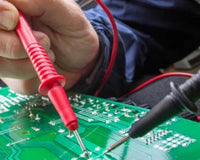
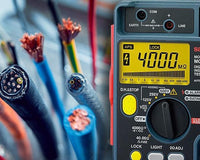
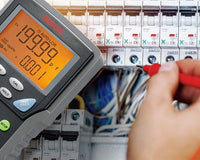
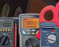
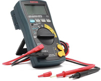
A multimeter is one of the essential tools when it comes to debugging electronic circuits and measuring electrical parameters.
They are very handy as they can measure voltage, current, resistance, and many other electrical quantities in one single instrument. Using a multimeter is super simple, all you have to do is to probe the circuit of interest and measure it in the correct mode.
Also See:
A note about multimeter safety:
Please refer to the instructions that came with your meter, and never overload your meter with a voltage that is higher than the range selected. Overloading can damage your meter and/or lead to electric shock hazard.
Voltage Measurement
Never use a measuring instrument for a measurement category higher than specified. Always select the appropriate range before applying current.
Current Measurement
Use special caution not to input voltage to the current measuring terminal in measurement.
Getting Started

Once you have unboxed your new multimeter, it’s time to test it. Every multimeter comes with two test leads that are inserted into their designated ports on the multimeter. The red test lead is for the positive potential and the black is for ground or the negative potential.
Once the test leads are in place users can now go onto the next step which is testing. To measure the desired quantity there are a couple of things users should keep in mind.
Choosing the Right Mode
Assuming a user wants to measure the resistance of a resistor, then it is necessary to adjust the multimeter to resistance mode. Choosing the wrong mode and range may lead to inaccurate results. Although there are many new multimeters that automatically detect the type of electrical parameter being measured and do not require the users to adjust the knob.

Since not all multimeters have the Auto-range feature that allows it to automatically detect the size of the electrical parameter being measured, adjusting the range is also very important for accurate and precise measurements. A 100K resistor cannot be measured in the 10KΩ range.
Basic Functions
There are many different functions and features a multimeter offers other than measuring the basic parameters (Voltage, current, resistance).
Continuity Test
This function is quite handy when it comes to testing shorts in connections or to trace a path in a circuit board. Assuming a user wants to test the continuity of a wire, place one test lead on one end of the wire and the other on the other end of the wire, and set the multimeter to the continuity mode. If the wire is shorted under the insulation the beeper on the instrument will turn on alerting the user otherwise it won’t.
Diode Test
Just as the name implies this function is used test diodes. When using this function make sure to turn off all the power sources connected with the diode. Place the test leads on the terminals of the diode. A good forward-biased diode displays a voltage drop ranging from 0.5 to 0.8 volts for the most commonly used silicon diodes. Some germanium diodes have a voltage drop ranging from 0.2 to 0.3 V.
A bad (opened) diode does not allow current to flow in either direction. A multimeter will display OL in both directions when the diode is opened.
Non Contact Voltage (NCV)
The NCV or the Non-contact voltage detection is a feature that most of the DMM’s offer. The main purpose of this feature allows users to detect live voltage in power lines without the need for making direct contact hence making it safe.
Data Hold & Relative Function
The Data hold function allows users to hold or pause a measurement on the screen making it convenient for the user to either note it down or avoid human error. The Relative function Stores existing reading (a delta) and resets display to zero. Sets a relative reference point to measure against the next reading.
MAX / MIN / AVG
The maximum value, the minimum value and the average value are displayed or recorded. The recorded value can be seen later on the display.


